CPF32K0800BHR36
| Model | CPF32K0800BHR36 |
| Description | Fixed Resistor, Metal Film, 3W, 2080ohm, 500V, 0.1% +/-Tol, 50ppm/Cel, Through Hole Mount, AXIAL LEADED |
| PDF file | Total 4 pages (File size: 104K) |
| Chip Manufacturer | VISHAY |


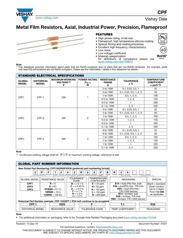
CPF
www.vishay.com
Vishay Dale
HISTORICAL TC CODE
T-9
T-2
T-1
T-0
T-00
TEMPERATURE COEFFICIENT
25 ppm/°C
50 ppm/°C
100 ppm/°C
150 ppm/°C
200 ppm/°C
TEMPERATURE COEFFICIENT CODES
GLOBAL TC CODE
E
H
K
L
N
TECHNICAL SPECIFICATIONS
PARAMETER
Rated Dissipation at 70 °C
Limiting Element Voltage
Insulation Voltage
Thermal Resistance
Insulation Resistance
Category Temperature Range
Note
(1)
Rated voltage
P
x
R
GLOBAL
MODEL
CPF1
L
1 max.
d
(1)
UNIT
W
V
V
eff
K/W
°C
CPF1
1
250
900
85
CPF2
2
350
900
60
10
10
-65 °C / +230 °C
CPF3
3
500
900
50
DIMENSIONS
1.50 ± 0.125
(1)
(38.10 ±
3.18)
L
D
DIMENSIONS
in inches (millimeters)
L
D
L
1 max.
d
0.240 ± 0.020 0.090 ± 0.008 0.310 0.025 ± 0.002
(6.10 ± 0.51) (2.29 ± 0.20) (7.87) (0.64 ± 0.05)
0.344 ± 0.031 0.145 ± 0.015 0.425 0.032 ± 0.002
(8.74 ± 0.79) (3.68 ± 0.38) (10.80) (0.81 ± 0.05)
0.555 ± 0.041 0.180 ± 0.015 0.650 0.032 ± 0.002
(14.10 ± 1.04) (4.57 ± 0.381) (16.51) (0.81 ± 0.05)
CPF2
CPF3
Note
(1)
Lead length for product in bulk pack. For product supplied in
tape and reel, the actual lead length would be based on the body
size, tape spacing and lead trim.
HEAT RISE (°C ABOVE AMBIENT)
% RATED POWER
120
100
80
60
40
250
CPF1
200
150
100
CPF2
CPF3
20
50
0
- 55
0
0
1
2
3
4
5
APPLIED POWER IN W
- 25
0
30
60
90
70
120
150 180
210
240
AMBIENT TEMP. IN °C
DERATING
THERMAL RESISTANCE
Note
• Surface temperatures were taken with an infrared pyrometer in
+25 °C still air. Resistors were supported by their leads in test
clips at a point 0.500" (12.70 mm) out from the resistor body
ends.
MATERIAL SPECIFICATIONS
Element
Core
Coating
Termination
Proprietary nickel-chrome alloy
Cleaned high purity ceramic
Special high temperature conformal coat
Standard lead material is solder-coated
Solderable and weldable per
MIL-STD-1276, Type C
MECHANICAL SPECIFICATIONS
Terminal Strength
2 pound pull test
Continuous satisfactory coverage
when tested in accordance with
MIL-STD-202, Method 208
Solderability
Revision: 15-Dec-16
Document Number: 31021
2
For technical questions, contact:
ff2aresistors@vishay.com
THIS DOCUMENT IS SUBJECT TO CHANGE WITHOUT NOTICE. THE PRODUCTS DESCRIBED HEREIN AND THIS DOCUMENT
ARE SUBJECT TO SPECIFIC DISCLAIMERS, SET FORTH AT
www.vishay.com/doc?91000


