L1005-FH1N0S
| Model | L1005-FH1N0S |
| Description | General Purpose Inductor, 0.001uH, 30%, 1 Element, Ceramic-Core, SMD |
| PDF file | Total 2 pages (File size: 32K) |
| Chip Manufacturer | TOKO |


40
TYPE
LL1005FH
Multilayer Chip Inductors
Meeting Your Needs
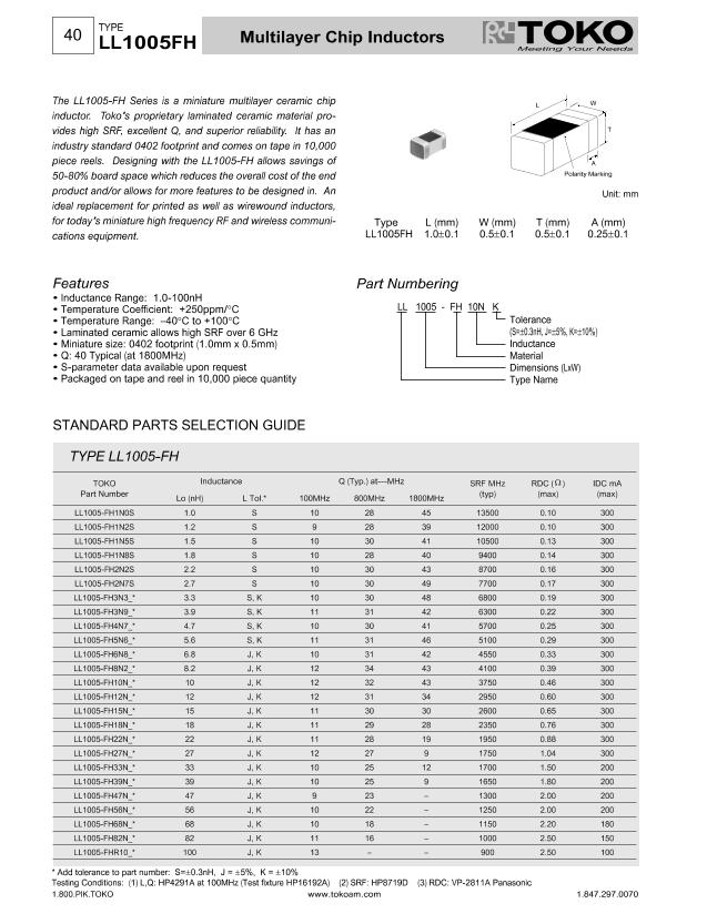
The LL1005-FH Series is a miniature multilayer ceramic chip
inductor. Toko's proprietary laminated ceramic material pro-
vides high SRF, excellent Q, and superior reliability. It has an
industry standard 0402 footprint and comes on tape in 10,000
piece reels. Designing with the LL1005-FH allows savings of
50-80% board space which reduces the overall cost of the end
product and/or allows for more features to be designed in. An
ideal replacement for printed as well as wirewound inductors,
for today's miniature high frequency RF and wireless communi-
cations equipment.
L
W
T
A
Polarity Marking
Unit: mm
Type
LL1005FH
L (mm)
1.0±0.1
W (mm)
0.5±0.1
T (mm)
0.5±0.1
A (mm)
0.25±0.1
Features
• Inductance Range: 1.0-100nH
• Temperature Coefficient: +250ppm/°C
• Temperature Range: –40°C to +100°C
• Laminated ceramic allows high SRF over 6 GHz
• Miniature size: 0402 footprint (1.0mm x 0.5mm)
• Q: 40 Typical (at 1800MHz)
• S-parameter data available upon request
• Packaged on tape and reel in 10,000 piece quantity
Part Numbering
LL 1005 - FH 10N K
Tolerance
(S=±0.3nH, J=±5%, K=±10%)
Inductance
Material
Dimensions
(LxW)
Type Name
STANDARD PARTS SELECTION GUIDE
TYPE LL1005-FH
TOKO
Part Number
LL1005-FH1N0S
LL1005-FH1N2S
LL1005-FH1N5S
LL1005-FH1N8S
LL1005-FH2N2S
LL1005-FH2N7S
LL1005-FH3N3_*
LL1005-FH3N9_*
LL1005-FH4N7_*
LL1005-FH5N6_*
LL1005-FH6N8_*
LL1005-FH8N2_*
LL1005-FH10N_*
LL1005-FH12N_*
LL1005-FH15N_*
LL1005-FH18N_*
LL1005-FH22N_*
LL1005-FH27N_*
LL1005-FH33N_*
LL1005-FH39N_*
LL1005-FH47N_*
LL1005-FH56N_*
LL1005-FH68N_*
LL1005-FH82N_*
LL1005-FHR10_*
Inductance
Lo (nH)
1. 0
1.2
1.5
1.8
2.2
2.7
3.3
3.9
4. 7
5. 6
6.8
8.2
10
12
15
18
22
27
33
39
47
56
68
82
100
L Tol.*
S
S
S
S
S
S
S, K
S, K
S, K
S, K
J, K
J, K
J, K
J, K
J, K
J, K
J, K
J, K
J, K
J, K
J, K
J, K
J, K
J, K
J, K
100MHz
10
9
10
10
10
10
10
11
10
11
10
12
12
12
11
11
11
12
10
10
9
10
10
11
13
Q (Typ.) at---MHz
800MHz
28
28
30
28
30
30
30
31
30
31
31
34
32
31
30
29
28
27
25
25
23
22
18
16
–
1800MHz
45
39
41
40
43
49
48
42
41
46
42
43
43
34
30
28
19
9
12
9
–
–
–
–
–
SRF MHz
(typ)
13500
12000
10500
9400
8700
7700
6800
6300
5700
5100
4550
4100
3750
2950
2600
2350
1950
1750
1700
1650
1300
1250
1150
1000
900
RDC (
Ω
)
(max)
0.10
0.10
0.13
0.14
0.16
0.17
0.19
0.22
0.25
0.29
0.33
0.39
0.46
0.60
0.65
0.76
0.88
1.04
1.50
1.80
2.00
2.00
2.20
2.50
2.50
IDC mA
(max)
300
300
300
300
300
300
300
300
300
300
300
300
300
300
300
300
300
300
200
200
200
200
180
150
100
* Add tolerance to part number: S=±0.3nH, J =
±5%,
K =
±10%
Testing Conditions: (1) L,Q: HP4291A at 100MHz (Test fixture HP16192A)
1.800.PIK.TOKO
(2) SRF: HP8719D
(3) RDC: VP-2811A Panasonic
1.847.297.0070
www.tokoam.com


