MLL4733D-1
| Model | MLL4733D-1 |
| Description | Zener Diode, 5.1V V(Z), 1%, 1W |
| PDF file | Total 3 pages (File size: 127K) |
| Chip Manufacturer | MICROSEMI |


1N4728UR-1 thru 1N4764AUR-1,e3
(or MLL4728A-1 thru MLL4764A-1,e3)
SCOTTSDALE DIVISION
METALLURGICALLY BONDED GLASS
SURFACE MOUNT 1.0 W ZENERS
DESCRIPTION
This surface mountable 1 watt Zener diode series is electrically equivalent to
the 1N4728A thru 1N4764A registration in the DO-41 equivalent package
except that it meets the JEDEC surface mount outline DO-213AB and also
includes enhanced internal contact design. It is an ideal selection for
applications of high density and low parasitic requirements for voltage
regulation. Standard voltage tolerance is +/-5% with tighter tolerances
available down to 1%. With its glass hermetic qualities, it may also be used
for high reliability applications when required by a source control drawing
(SCD).
IMPORTANT:
For the most current data, consult
MICROSEMI’s
website:
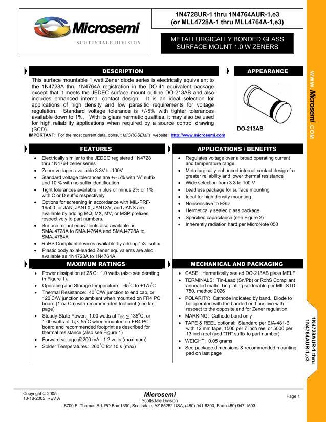
APPEARANCE
WWW .
Microsemi
.C
OM
DO-213AB
FEATURES
•
•
•
•
•
Electrically similar to the JEDEC registered 1N4728
thru 1N4764 zener series
Zener voltages available 3.3V to 100V
Standard voltage tolerances are +/- 5% with “A” suffix
and 10 % with no suffix identification
Tight tolerances available in plus or minus 2% or 1%
with C or D suffix respectively
Options for screening in accordance with MIL-PRF-
19500 for JAN, JANTX, JANTXV, and JANS are
available by adding MQ, MX, MV, or MSP prefixes
respectively to part numbers.
Surface mount equivalents also available as
SMAJ4728A to SMAJ4764A and SMAJ4728A to
SMAJ4764A
RoHS Compliant devices available by adding “e3” suffix
Plastic body axial-leaded Zener equivalents are also
available as 1N4728A to 1N4764A
•
•
•
•
•
•
•
•
•
APPLICATIONS / BENEFITS
Regulates voltage over a broad operating current
and temperature range
Metallurgically enhanced internal contact design fro
greater reliability and lower thermal resistance
Wide selection from 3.3 to 100 V
Leadless package for surface mounting
Ideal for high density mounting
Nonsensitive to ESD
Hermetically sealed glass package
Specified capacitance (see Figure 2)
Inherently radiation hard per MicroNote 050
•
•
•
MAXIMUM RATINGS
•
•
•
Power dissipation at 25
º
C: 1.0 watts (also see derating
in Figure 1).
Operating and Storage temperature: -65
º
C to +175
º
C
Thermal Resistance: 40
º
C/W junction to end cap, or
120
º
C/W junction to ambient when mounted on FR4 PC
board (1 oz Cu) with recommended footprint (see last
page)
Steady-State Power: 1.00 watts at T
EC
< 135
o
C, or
1.00 watts at T
A
< 55
º
C when mounted on FR4 PC
board and recommended footprint as described for
thermal resistance (also see Figure 1)
Forward voltage @200 mA: 1.2 volts (maximum)
º
Solder Temperatures: 260 C for 10 s (max)
MECHANICAL AND PACKAGING
•
CASE: Hermetically sealed DO-213AB glass MELF
•
TERMINALS: Tin-Lead (Sn/Pb) or RohS Compliant
annealed matte-Tin plating solderable per MIL-STD-
750, method 2026
•
POLARITY: Cathode indicated by band. Diode to
be operated with the banded end positive with
respect to the opposite end for Zener regulation
•
MARKING: Cathode band only
•
TAPE & REEL optional: Standard per EIA-481-B
with 12 mm tape, 1500 per 7 inch reel or 5000 per
13 inch reel (add “TR” suffix to part number)
•
WEIGHT: 0.05 grams
•
See package dimensions & recommended mounting
pad on last page
•
1N4728AUR-1 thru
1N4764AUR-1,e3
•
•
Copyright
©
2005
10-18-2005 REV A
Microsemi
Scottsdale Division
8700 E. Thomas Rd. PO Box 1390, Scottsdale, AZ 85252 USA, (480) 941-6300, Fax: (480) 947-1503
Page 1


