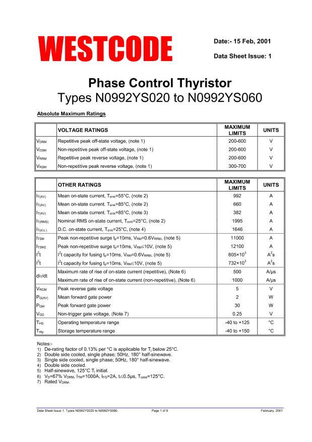
N0992YS050
| Model | N0992YS050 |
| Description | Silicon Controlled Rectifier, 1995A I(T)RMS, 1646000mA I(T), 500V V(DRM), 500V V(RRM), 1 Element, 101A335, 3 PIN |
| PDF file | Total 9 pages (File size: 94K) |
| Chip Manufacturer | IXYS |

WESTCODE
Positive development in power electronics
5.2 Calculating V
T
using ABCD Coefficients
N0992YS020 to N0992YS060
The on-state characteristic I
T
vs. V
T
, on page 7 is represented in two ways;
(i)
the well established V
o
and r
s
tangent used for rating purposes and
(ii)
a set of constants A, B, C, D, forming the coefficients of the representative equation for V
T
in
terms of I
T
given below:
V
T
=
A
+
B
⋅
ln
(
I
T
)
+
C
⋅
I
T
+
D
⋅
I
T
The constants, derived by curve fitting software, are given below for both hot and cold characteristics. The
resulting values for V
T
agree with the true device characteristic over a current range which is limited to that
plotted.
125°C Coefficients
A
B
C
D
5.3 D.C. Thermal Impedance Calculation
−
t
τ
r
t
=
∑
r
p
⋅
1
−
e
p
p
=
1
p
=
n
-0.1754018
0.2037886
3.061740×10
-4
-0.01514247
Where
p = 1
to
n, n
is the number of terms in the series and:
t = Duration of heating pulse in seconds.
r
t
= Thermal resistance at time t.
r
p
= Amplitude of p
th
term.
τ
p
= Time Constant of r
th
term.
D.C. Double Side Cooled
Term
R
p
1
0.12000552
0.3391689
2
0.01609235
0.09405764
3
8.812673×10
0.12195269
-3
4
3.659765×10
2.196197×10
-3
-3
τ
p
D.C. Single Side Cooled
Term
R
p
1
0.06157697
2.136132
2
8.431182×10
1.212898
-3
3
0.01031315
0.1512408
4
0.01613806
0.04244
5
5.181088×10
-3
-3
τ
p
2.889595×10
Data Sheet Issue 1. Types N0992YS020 to N0992YS060.
Page 4 of 9
February, 2001


