SMBJ43AE3/TR
| Model | SMBJ43AE3/TR |
| Description | Trans Voltage Suppressor Diode, 600W, 43V V(RWM), Unidirectional, 1 Element, Silicon, DO-214AA, ROHS COMPLIANT, PLASTIC PACKAGE-2 |
| PDF file | Total 4 pages (File size: 177K) |
| Chip Manufacturer | MICROSEMI |


SMBJ5.0 thru SMBJ170A, CA, e3
and SMBG5.0 thru SMBG170A, CA, e3
SCOTTSDALE DIVISION
SURFACE MOUNT 600 Watt
Transient Voltage Suppressor
DESCRIPTION
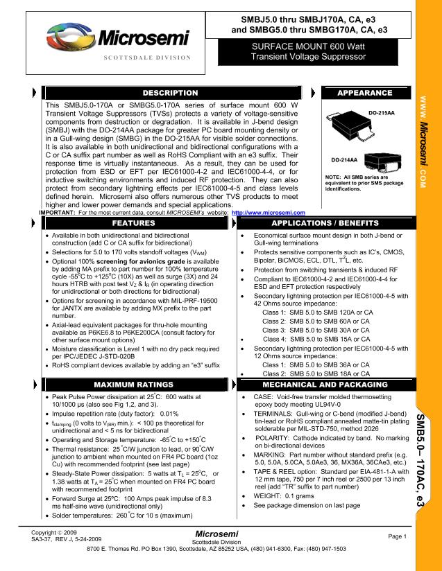
This SMBJ5.0-170A or SMBG5.0-170A series of surface mount 600 W
Transient Voltage Suppressors (TVSs) protects a variety of voltage-sensitive
components from destruction or degradation. It is available in J-bend design
(SMBJ) with the DO-214AA package for greater PC board mounting density or
in a Gull-wing design (SMBG) in the DO-215AA for visible solder connections.
It is also available in both unidirectional and bidirectional configurations with a
C or CA suffix part number as well as RoHS Compliant with an e3 suffix. Their
response time is virtually instantaneous. As a result, they can be used for
protection from ESD or EFT per IEC61000-4-2 and IEC61000-4-4, or for
inductive switching environments and induced RF protection. They can also
protect from secondary lightning effects per IEC61000-4-5 and class levels
defined herein. Microsemi also offers numerous other TVS products to meet
higher and lower power demands and special applications.
IMPORTANT:
For the most current data, consult
MICROSEMI’s
website:
APPEARANCE
WWW .
Microsemi
.C
OM
NOTE: All SMB series are
equivalent to prior SMS package
identifications.
FEATURES
•
Available in both unidirectional and bidirectional
construction (add C or CA suffix for bidirectional)
•
Selections for 5.0 to 170 volts standoff voltages (V
WM
)
•
Optional 100%
screening for avionics grade
is available
by adding MA prefix to part number for 100% temperature
cycle -55
o
C to +125
o
C (10X) as well as surge (3X) and 24
hours HTRB with post test V
Z
& I
R
(in operating direction
for unidirectional or both directions for bidirectional)
•
Options for screening in accordance with MIL-PRF-19500
for JANTX are available by adding MX prefix to the part
number.
•
Axial-lead equivalent packages for thru-hole mounting
available as P6KE6.8 to P6KE200CA (consult factory for
other surface mount options)
•
Moisture classification is Level 1 with no dry pack required
per IPC/JEDEC J-STD-020B
•
RoHS compliant devices available by adding an “e3” suffix
•
•
•
•
•
APPLICATIONS / BENEFITS
Economical surface mount design in both J-bend or
Gull-wing terminations
Protects sensitive components such as IC’s, CMOS,
2
Bipolar, BiCMOS, ECL, DTL, T L, etc.
Protection from switching transients & induced RF
Compliant to IEC61000-4-2 and IEC61000-4-4 for
ESD and EFT protection respectively
Secondary lightning protection per IEC61000-4-5 with
42 Ohms source impedance:
Class 1: SMB 5.0 to SMB 120A or CA
Class 2: SMB 5.0 to SMB 60A or CA
Class 3: SMB 5.0 to SMB 30A or CA
Class 4: SMB 5.0 to SMB 15A or CA
Secondary lightning protection per IEC61000-4-5 with
12 Ohms source impedance:
Class 1: SMB 5.0 to SMB 36A or CA
Class 2: SMB 5.0 to SMB 18A or CA
•
•
•
MAXIMUM RATINGS
•
Peak Pulse Power dissipation at 25
º
C: 600 watts at
10/1000
μs
(also see Fig 1,2, and 3).
•
Impulse repetition rate (duty factor): 0.01%
•
t
clamping
(0 volts to
V
(BR)
min.): < 100 ps theoretical for
unidirectional and < 5 ns for bidirectional
•
Operating and Storage temperature: -65
º
C to +150
º
C
•
Thermal resistance: 25
º
C/W junction to lead, or 90
º
C/W
junction to ambient when mounted on FR4 PC board (1oz
Cu) with recommended footprint (see last page)
o
•
Steady-State Power dissipation: 5 watts at T
L
= 25 C, or
1.38 watts at T
A
= 25
º
C when mounted on FR4 PC board
with recommended footprint
•
Forward Surge at 25ºC: 100 Amps peak impulse of 8.3
ms half-sine wave (unidirectional only)
•
Solder temperatures: 260
º
C for 10 s (maximum)
Copyright
©
2009
SA3-37, REV J, 5-24-2009
MECHANICAL AND PACKAGING
•
•
CASE: Void-free transfer molded thermosetting
epoxy body meeting UL94V-0
TERMINALS: Gull-wing or C-bend (modified J-bend)
tin-lead or RoHS compliant annealed matte-tin plating
solderable per MIL-STD-750, method 2026
POLARITY: Cathode indicated by band. No marking
on bi-directional devices
MARKING: Part number without standard prefix (e.g.
5.0, 5.0A, 5.0CA, 5.0Ae3, 36, MX36A, 36CAe3, etc.)
TAPE & REEL option: Standard per EIA-481-1-A with
12 mm tape, 750 per 7 inch reel or 2500 per 13 inch
reel (add “TR” suffix to part number)
WEIGHT: 0.1 grams
See package dimension on last page
SMB5.0– 170AC, e3
•
•
•
•
•
Microsemi
Scottsdale Division
8700 E. Thomas Rd. PO Box 1390, Scottsdale, AZ 85252 USA, (480) 941-6300, Fax: (480) 947-1503
Page 1


