U.FL-R-1
| Model | U.FL-R-1 |
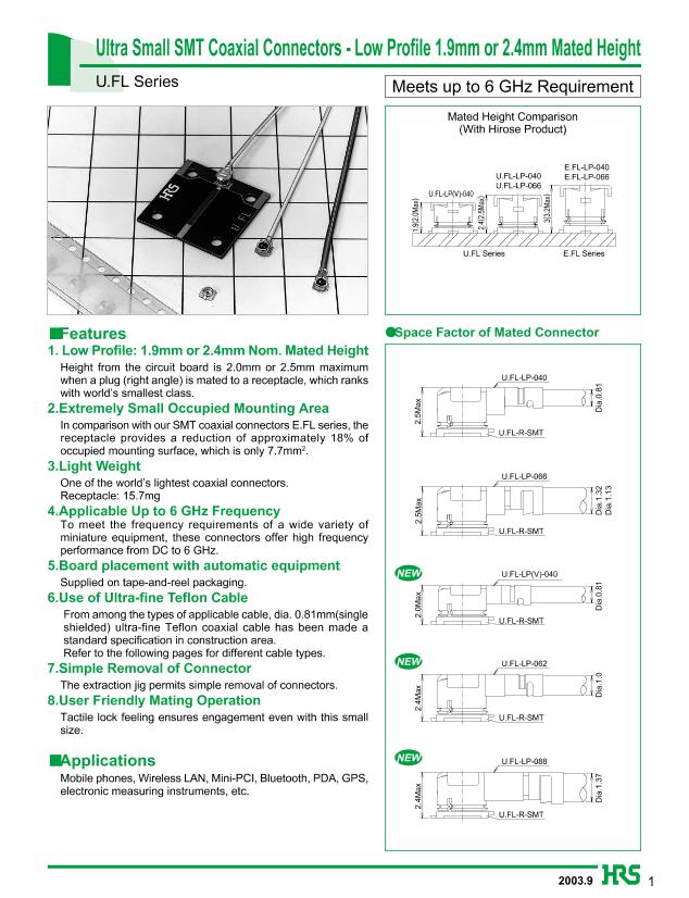
| Description | Ultra Small SMT Coaxial Connectors - Low Profile 1.9mm or 2.4mm Mated Height |
| PDF file | Total 8 pages (File size: 178K) |
| Chip Manufacturer | HRS |


sUsage
Precautions
1. Plugs
1) To disconnect connectors, hook the end portion of U.FL-LP-N-2 and U.FL-LP(V)-N-2 onto the connector cover and
pull off vertically in the direction of the connector mating axis.
1)
To remove the connector directly, hold the connector cover and pull off
Extraction Jig
vertically in the direction of the connector mating axis.
U.FL Cable
(Please exercise caution so as not to injure fingertips or nails.)
Assembly
2) To mate the connectors, the mating axes of both connectors are aligned
and the connectors are inserted as perpendicularly as possible.
Do not attempt to insert on an extreme angle.
U.FL-R-SMT
(1) Connection/
disconnection of
connectors
After the connectors are mating, do not apply a load to the cable in excess of the values indicated in the diagram
below.
U.FL-LP-040
U.FL-R-SMT
4N max.
2N max.
(2) Permissible load on
the cable after
connector mating.
2N max.
(3) Precautions
Do NOT forcefully twist or deform wires.
2. Receptacles
(1) Recommended
temperature profile
(Reference)
(℃)
260
240
220
200
180
160
140
120
100
80
Heating peak
240℃ 3 seconds
Temperature on
Top Portion of Part
Preheating 183℃
(130 to 165℃)
40 to 50
seconds
Within 2 minutes
Time
1) The temperature profile indicates the board surface temperature at the point of contacts with the connector
terminals (for surface mounted receptacle).
2) The temperature profile will change depending on conditions which include such factors as the size of the board,
the solder used, and the solder thickness.
(2) Recommended
manual soldering
(Reference)
Manual soldering: 350˚C for 5 seconds
(3) Recommended screen
0.1 to 0.15 mm
thickness
6


