Y078673K2000F9L
| Model | Y078673K2000F9L |
| Description | Fixed Resistor, Metal Foil, 0.6W, 73200ohm, 300V, 1% +/-Tol, -1,1ppm/Cel, 3011, |
| PDF file | Total 6 pages (File size: 106K) |
| Chip Manufacturer | VISHAY |


S Series
Vishay Foil Resistors
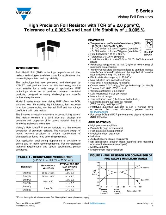
FIGURE 2 - STANDARD IMPRINTING AND DIMENSIONS
Front View
L
VISHAY
XXXX
S102C
Date Code
01
10
Year
Week
ST
1)
W
Rear View
Optional Customer Part
Number
Print specification, etc. if required
XXXXXX
100R01
0.01
%
Resistance
Value
Code
Tolerance
H
Model
Number
LS
SW
Lead Material #22 AWG
Round Solder Coated Copper
LL
Note
1. The standoffs shall be so located as to give a lead clearance of 0.010" minimum between the resistor body and the printed circuit board
when the standoffs are seated on the printed circuit board. This is to allow for proper cleaning of flux and other contaminants from the unit
after all soldering processes.
TABLE 2 - MODEL SELECTION
MODEL
NUMBER
AMBIENT
RESISTANCE MAXIMUM POWER RATING AVERAGE
WEIGHT
RANGE
WORKING
IN GRAMS
(Ω)
VOLTAGE
at
at
+ 70 °C + 125 °C
1 to 150K
300
1 to 100K
0.6 W
0.3 W
up to 100K
0.4 W
0.2 W
over 100K
1.0 W
0.5 W
up to 200K
0.6 W
0.3 W
over 200K
1.5 W 0.75 W
up to 300K
0.8 W
0.4 W
over 300K
2.0 W
1.0 W
up to 400K
1.0 W
0.5 W
over 400K
DIMENSIONS
INCHES
W: 0.105 ± 0.010
L: 0.300 ± 0.010
H: 0.326 ± 0.010
ST: 0.010 min.
SW: 0.035 ± 0.010
LL: 1.000 ± 0.125
LS: 0.150 ± 0.0054
W: 0.160 max.
L: 0.575 max.
H: 0.413 max.
ST: 0.035 ± 0.005
SW: 0.050 ± 0.005
LL: 1.000 ± 0.125
LS: 0.400 ± 0.020
W: 0.160 max.
L: 0.820 max.
H: 0.413 max.
ST: 0.035 ± 0.005
SW: 0.050 ± 0.005
LL: 1.000 ± 0.125
LS: 0.650 ± 0.020
W: 0.260 max.
L: 1.200 max.
H: 0.413 max.
ST: 0.035 ± 0.005
SW: 0.050 ± 0.005
LL: 1.000 ± 0.125
LS: 0.900 ± 0.020
mm
F
(1)
(INCHES)
TIGHTEST
TOLERANCE
VS. LOWEST
RESISTANCE
VALUE
S102C
(S102J)
(2)
S102K
(S102L)
(2)
S104D
(S104F)
(1)
0.6
1 to 500K
350
1.4
S104K
1 to 300K
S105D
(S105F)
(1)
1 to 750K
350
1.9
S105K
1 to 500K
S106D
0.5 to 1M
500
4.0
S106K
0.5 to 600K
2.67 ± 0.25
7.62 ± 0.25
8.28 ± 0.25
0.254 min.
1.02 ± 0.13
25.4 ± 3.18
3.81 ± 0.13
4.06 max.
14.61 max.
(0.138)
10.49 max.
(0.565)
0.889 ± 0.13
(0.413)
1.27 ± 0.13
25.4 ± 3.18
10.16 ± 0.51
(0.138)
4.06 max.
(0.890)
20.83 max.
(0.413)
10.49 max.
0.889 ± 0.13
1.27 ± 0.13
25.4 ± 3.18
16.51 ± 0.51 (0.7 ± 0.05)
6.60 max.
30.48 max.
10.49 max.
0.889 ± 0.13
1.27 ± 0.13
25.4 ± 3.18
22.86 ± 0.51
0.005 %/50
Ω
0.01 %/25
Ω
0.02 %/12
Ω
0.05 %/5
Ω
0.1 %/2
Ω
0.50 %/1
Ω
Notes
(1)
S104F and S105F have different package dimensions (see last column). All other specifications are the same.
(2)
0.200" (5.08 mm) lead spacing available - specify S102J for S102C, and S102L for S102K.
www.vishay.com
2
For any questions, contact:
foil@vishay.com
Document Number: 63001
Revision: 25-Jun-09


