Y161210R6000C9R
| Model | Y161210R6000C9R |
| Description | Fixed Resistor, Metal Foil, 0.4W, 10.6ohm, 220V, 0.25% +/-Tol, 2ppm/Cel, Surface Mount, 2512, CHIP, ROHS COMPLIANT |
| PDF file | Total 4 pages (File size: 381K) |
| Chip Manufacturer | VISHAY |


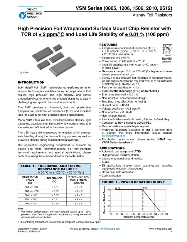
VSM Series (0805, 1206, 1506, 2010, 2512)
Vishay Foil Resistors
FIGURE 2 - TRIMMING TO VALUES
(Conceptual Illustration)
FIGURE 3 - TYPICAL RESISTANCE/
TEMPERATURE CURVE
(For more Details, see Table 1)
+ 150
+ 100
Interloop Capacitance
Reduction in Series
Current Path
Before Trimming
Current Path
After Trimming
Trimming Process
Removes this Material
from Shorting Strip Area
Changing Current Path
and Increasing
Resistance
Δ
R
+ 50
± 2 ppm/°C
(+ 25 °C reference)
0
R
(ppm)
- 50
- 100
- 150
- 200
- 50
- 25
0
+ 25
+ 50
+ 75
+ 100 + 125
- 55
Ambient Temperature (°C) and TCR Chord Slopes for
Different Temperature Ranges
Mutual Inductance
Reduction due
to Change in
Current Direction
Note:
Foil shown in
black,
etched spaces in
white
Note
• The TCR values for < 100
Ω
are influenced by the termination
composition and result in deviation from this curve.
TABLE 2 - DIMENSIONS AND LAND PATTERN
in Inches (Millimeters)
Top View
L
X
T
D
CHIP SIZE
0805
1206
1506
2010
2512
L
± 0.005 (0.13)
0.080 (2.03)
0.126 (3.20)
0.150 (3.81)
0.198 (5.03)
0.249 (6.32)
W
± 0.005 (0.13)
0.050 (1.27)
0.062 (1.57)
0.062 (1.57)
0.097 (2.46)
0.127 (3.23)
THICKNESS
MAXIMUM
0.025 (0.64)
0.025 (0.64)
0.025 (0.64)
0.025 (0.64)
0.025 (0.64)
D
± 0.005 (0.13)
0.015 (0.38)
0.020 (0.51)
0.020 (0.51)
0.025 (0.64)
0.032 (0.81)
Z
(1)
0.122 (3.10)
0.175 (4.45)
0.199 (5.05)
0.247 (6.27)
0.291 (7.39)
G
(1)
0.028 (0.71)
0.059 (1.50)
0.083 (2.11)
0.115 (2.92)
0.150 (3.81)
X
(1)
0.050 (1.27)
0.071 (1.80)
0.071 (1.80)
0.103 (2.62)
0.127 (3.23)
Recommended Land Pattern
Footprint
W
Z
G
Note
(1)
Land pattern dimensions are per IPC-7351A
TABLE 3 - SPECIFICATIONS
CHIP SIZE
0805
1206
1506
2010
2512
RATED POWER (mW)
at + 70 °C
100
150
200
300
400
MAX. WORKING VOLTAGE
(≤
P
×
R
)
28 V
61 V
78 V
145 V
220 V
RESISTANCE RANGE
(Ω)
10 to 8K
10 to 25K
10 to 30K
10 to 70K
10 to 125K
MAXIMUM WEIGHT
(mg)
6
11
12
27
40
TABLE 4 - PERFORMANCES
MIL-PRF-55342
CHARACTERISTIC E
ΔR
LIMITS
Thermal Shock, 100 x (- 65 °C to + 150 °C)
± 0.1 %
Low Temperature Operation, - 65 °C, 45 min at P
nom
± 0.1 %
Short Time Overload, 6.25 x Rated Power, 5 s
± 0.1 %
High Temperature Exposure, + 150 °C, 100 h
± 0.1 %
Resistance to Soldering Heat
± 0.2 %
Moisture Resistance
± 0.2 %
Load Life Stability + 70 °C for 2000 h at Rated Power
± 0.5 %
TEST OR CONDITIONS
Note
(1)
As shown + 0.01
Ω
to allow for measurement errors at low values.
www.foilresistors.com
2
For any questions, contact:
foil@vishaypg.com
Document Number: 63070
Revision: 25-Mar-10
TYPICAL
ΔR
LIMITS
± 0.005 % (50 ppm)
± 0.01 % (100 ppm)
± 0.01 % (100 ppm)
± 0.01 % (100 ppm)
± 0.005 % (50 ppm)
± 0.005 % (50 ppm)
± 0.005 % (50 ppm)
MAXIMUM
ΔR
LIMITS
(1)
± 0.02 % (200 ppm)
± 0.02 % (200 ppm)
± 0.02 % (200 ppm)
± 0.03 % (300 ppm)
± 0.01 % (100 ppm)
± 0.03 % (300 ppm)
± 0.01 % (100 ppm)


