M11L416256A-25T
| Model | M11L416256A-25T |
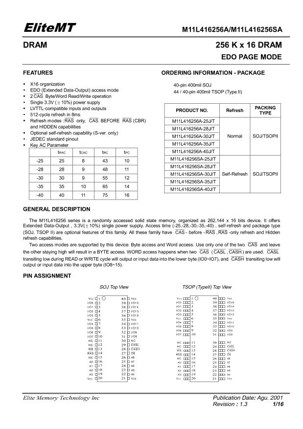
| Description | EDO DRAM, 256KX16, 25ns, CMOS, PDSO40, TSOP2-44/40 |
| PDF file | Total 16 pages (File size: 231K) |
| Chip Manufacturer | ESMT |


(OLWH07
ABSOLUTE MAXIMUM RATINGS
Voltage on Any pin Relative to Vss … ……-0.5V to +4.6V
Operating Temperature, T
A
(ambient) ….0
°
C to +70
°
C
Storage Temperature (plastic) ……….-55
°
C to +150
°
C
Power Dissipation …………………………………0.8W
Short Circuit Output Current ……………………50mA
M11L416256A/M11L416256SA
Permanent device damage may occur if “Absolute
Maximum Ratings” are exceeded. This is a stress rating
only, and functional operation of the device above those
conditions indicated in the operational sections of this
specification is not implied. Exposure to absolute
maximum rating conditions for extended periods may
affect reliability.
DC ELECTRICAL CHARACTERISTICS AND RECOMMENDED
OPERATING CONDITIONS
(0
°
C
≤
T
A
≤
70
°
C ; V
CC
= 3.3V
±
10% unless otherwise noted)
PARAMETER
Supply Voltage
Supply Voltage
Input High Voltage
Input Low Voltage
Input Leakage Current
Output Leakage Current
Output High Voltage
Output Low Voltage
Note : 1.All Voltages referenced to V
SS
0V
≤
V
IN
≤
V
IH
(max)
0V
≤
V
OUT
≤
V
CC
Output(s) disable
I
OH
= -2 mA
I
OL
= 2 mA
CONDITIONS
SYMBOL
V
CC
V
SS
V
IH
V
IL
I
LI
I
LO
V
OH
V
OL
MIN
3.0
0
2.0
-0.3
-10
-10
2.4
-
MAX
3.6
0
V
CC
+0.3
0.8
10
10
-
0.4
UNITS NOTES
V
V
V
V
µ
A
µ
A
V
V
1
1
1
PARAMETER
Operating Current
Standby Current
CONDITIONS
RAS
,
CAS
cycling , t
RC
=min
SYMBOL
I
CC1
I
CC2
MAX
-25
-28
-30
-35
-40
UNITS NOTES
mA
mA
mA
mA
mA
mA
mA
µ
A
2
1,3
1
1,2
210 190 170 150 135
4
2
4
2
4
2
4
2
4
2
TTL interface ,
RAS
,
CAS
= V
IH
,
D
OUT
=High-Z
CMOS interface,
RAS
,
CAS
≥
V
CC
-0.2V
RAS
only refresh Current
t
RC
= min
t
PC
= min
RAS
=V
IH
,
CAS
= V
IL
I
CC3
I
CC4
I
CC5
I
CC6
I
CC7
210 190 170 150 135
210 190 170 150 135
5
5
5
5
5
EDO Page Mode Current
Standby Current
CAS
Before
RAS
Refresh
Current
t
RC
= min
RAS
,
CAS
≤
0.2V, D
OUT
= High-Z,
210 190 170 150 135
400 400 400 400 400
Battery Backup Current
(S-ver. only)
Self Refresh Current
(S-ver. only)
CMOS interface
RAS
=
CAS
= V
IL
,
WE
=
OE
= A0~A8 = V
CC
-0.2 or 0.2V
DQ0~DQ15 = V
CC
-0.2, 0.2V or open
I
CC8
400 400 400 400 400
µ
A
Note
:
1. I
CC
max is specified at the output open condition.
2. Address can be changed twice or less while
RAS
=V
IL .
3. Address can be changed once or less while
CAS
=V
IH
.
Elite Memory Technology Inc
Publication Date: Agu. 2001
Revision
:
1.3
3/16


