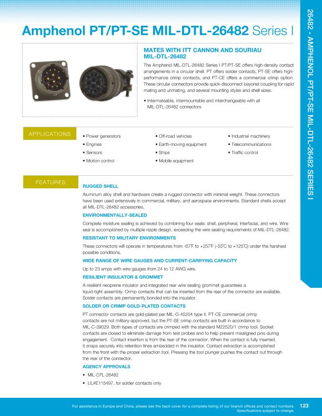
PT0512-4S-025
| Model | PT0512-4S-025 |
| Description | MIL Series Connector, |
| PDF file | Total 24 pages (File size: 5M) |
| Chip Manufacturer | AMPHENOL |

26482 - AMPHENOL PT/PT-SE MIL-DTL-26482 SERIES I
AS SE MBLY IN S T RU C T IO NS
INSERTION OF CONTACTS
STEP 1:
Slide the rear accessories
over the wire bundle in the proper
sequence for re-assembly: cable
clamp and/or endbell first, then
ferrule, and coupling nut.
STEP 2:
Use the proper insertion tool
from the Contact Selection Chart on
slide the tool over the wire
side of the contact until the tool
bottoms on the contact.The tool for size
16 contacts presses against the shoulder
of the contact. The rear, or insulation
support, of the size 20 contacts presses
against an internal shoulder in the
tool tip.
STEP 3:
Dip the contact and tool tip in
isopropyl alcohol (do not use any lubricant
other than isopropyl alcohol). Hold the tool
perpendicular to the rear of the connector.
Beginning with the center cavity and
working outwards in a circular pattern,
insert the wired contact into the rear of
the connector until the contact snaps into
place. A light pull on the wire will ensure
that the contact is locked securely.
SIZE
8, 10, 12, 14
16, 18
20, 22, 24
TORQUE
(INCH/LBS)
10 - 15
15- 25
25 - 35
STEP 4:
Fill any unused cavities with
contacts. A wire hole filler must be
inserted into the grommet behind the
unused contacts to maintain the sealing
integrity of the connector.
STEP 5:
Check the mating face of the
connector to ensure that all the same
size contacts are on the same plane (fully
inserted). If not, the contact is not fully
inserted. Remove the contact using the
proper extraction tool and procedure and
re-insert. Do not attempt to reinsert the
insertion tool to correct the problem.
STEP 6:
Fixture the connector for
re-assembly using the endbell assembly
tools on
or a mating
connector with contacts installed. Slide
the connector accessories back down the
cable over the rear of the connector and
tighten. Torque as shown above.
EXTRACTION OF CONTACTS
STEP 1:
Remove the endbell
accessories and slide them
back over the wires.
STEP 2:
Use the proper
extraction tool from the chart
on
STEP 3:
On the mating face
of the connector, insert the
tool over the contact and
into the insulator until the tool
bottoms. While keeping an even
pressure against the tool, push
the plunger on the tool shaft
forward with your thumb and
index finger. This will release
the contact from the retention
tine and push it toward the rear
of the connector.
STEP 4:
Carefully remove
the extraction tool from the
connector. Pull the wire by
hand to completely remove
the contact from the rear of
the connector.
For assistance in Europe and China, please see the back cover for a complete listing of our branch offices and contact numbers.
Specifications subject to change.
145


