Calculation and Quality Judgment of Rectifier Diode
When designing a rectifier diode circuit, it is very important to select a rectifier diode with appropriate performance parameters. Take the actual design circuit as an example.
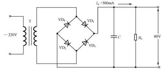
It can be seen from the figure that the AC input terminal is: 220V/50HZ, the rectified output DC voltage is required to be UO=60V, and the load current is IO=500mA; the following are two calculation methods:
1. Calculate the DC current flowing through the rectifier diode
Since a diode bridge rectifier circuit is used, the current passing through each pair of diodes should be 1/2 of the load current, and the two diodes in each pair are connected in series, and the current passing through each diode is also 1/2 of the load current. 2. Therefore, the forward current ID of the selected diode should be;

2. Calculate the reverse voltage URM of the rectifier diode
First of all, the effective value E2 of the secondary AC voltage of the transformer under the condition of satisfying the 45V output DC voltage should be determined. According to the empirical formula of the filter capacitor for voltage boost, the calculation expressions of UO and E2 are as follows:
The reverse voltage URM of the rectifier diode is calculated as:

According to the calculated values of ID and URM, select the tube that is close to the calculated value in the diode manual.
Quality judgment of rectifier diodes:
The judgment of the performance quality of junction diodes can be mainly divided into the following categories:
1. Device test method
Use a multimeter to test the junction diode device as shown in the figure below:

During the test, the forward connection method and reverse connection method as shown in the figure are adopted, and the reverse connection method of the black meter is adopted. The test results are as shown in the figure below:

Note: When performing the "diode" gear test in the reverse connection method, although the reverse leakage electrode of the diode is small, due to the large reverse resistance, according to Ohm's law U=IR, the reverse voltage at both ends of the diode is still relatively large, generally It is about 3V, but why "display no response"? This is because when Zi ah designed the "diode" file of the digital multimeter, in order to facilitate the test of the polarity of the diode, this file is specially used as 2V, so that the measured voltage 3>2V will be overloaded during the reverse polarity test, so This is display unresponsive, the display still shows overload. Undoubtedly, this provides convenience for accurately judging the polarity of the diode, short circuit between poles, and open circuit.
2. Performance quality test example
There are three main purposes of testing:
-Judge whether it is broken down and short circuited due to overvoltage
-Whether the internal PN junction is open due to overcurrent
-Whether it works under critical power usage to make it overheat and degrade its performance
The above three situations can cause the diode to lose its normal function in the circuit and cause the circuit to malfunction.
Before testing the above circuit, you should first have a clear understanding of the working principle of the circuit where the diode is located, for example: this diode acts as a rectifier in the circuit, or as a clamp, limiter, bias, protection or other functions, You should also be aware of the working voltage and current properties, size, and direction of the diode. Only in this way can the testing work be done with confidence.
During the test, it is necessary to analyze the position and connection relationship of the surrounding related components, and basically determine what impact they will have on the measurement results of the diode. As shown in the figure above, for the diode VD1, the resistors R1 and R3 are connected in parallel with VD1 at 23KΩ after being connected in series. The forward resistance of VD1 is 18KΩ, and the measured value of its forward resistance RAB≈10KΩ is normal at this time (at this time, the internal resistance of the two transistors is very large under static conditions, so there is no need to consider it); while the measurement of the reverse resistance is due to VD1 being normal. Make its reverse resistance very large. It should be the series value of R1 and R3, that is, RBA≈23KΩ is normal. If the measurement result; RAB≈RBA≈23KΩ. It means that VD1 is open circuit; RAB=RBA=0, it means that VD1 breaks down. For diode VD2, the situation is slightly different. Because a capacitor is separated, the static measurement of VD2 is much more intuitive and simple.
It is often encountered in the test of bridge rectifier circuit. If the fuse is intact, generally none of the four diodes in the bridge circuit is damaged. A digital multimeter can be used for routine testing of each tube. If the fuse has been blown, it can basically be concluded that a pair of rectifier diodes is damaged when it has been confirmed that it has nothing to do with the load, and a bunch of tubes will be short-circuited during measurement.
The above is the description of rectifier diode calculation and quality judgment, I hope it can bring you some help.
Copyright & Disclaimer
All works on this website that state "Source: ICMoment", all copyright belongs to ICMoment, please
specify
icmoment, https://www.icmoment.com, violators will be investigated for related The website will be held
legally responsible.
This website reproduces and indicates works from other sources, the purpose is to pass on more
information,
does not mean that the network agrees with its views or to confirm the authenticity of its content, does
not
assume direct responsibility for such works of infringement and joint and several liability. When other
media, websites or individuals reprint from this website, they must retain the source of the work
indicated
on this website and bear their own legal responsibility for copyright and other issues.
If the content of the work, copyright and other issues are involved, please contact us within one week from the date of publication of the work, otherwise it is regarded as a waiver of the relevant rights.
Related Readings
Popular Circuit Diagrams
Special Sale
Model
Price
