Electronics Course - Part 3 - Circuit Diagrams - Basic
In Part 2, we made a very simple circuit, so simple that we could describe it, and you could build it. As things get more complex, a description of the circuit becomes less workable. To overcome this, we can draw the circuit.
In the same way that the map of the London Underground shows all the connections, but not the exact positions of stations, a circuit diagram gives all the detail to create your own version of the circuit.
Circuit diagrams use symbols to represent the different parts, our basic LED circuit would use these symbols

The circuit drawn as a circuit diagram looks like this;
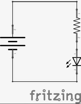
To draw the circuit, I am using open source software called "fritzing" feel free to download it here
The "dots" between the parts show that the parts are connected together.
From the diagram, we can build the circuit, an easy way to do this is with "breadboard", a solder-less method of connecting all our parts together. I created a youtube video explaining how breadboard works, so I won't repeat it, just take a look.
We can use Fritzing to show how the circuit will look on breadboard, here is our basic LED circuit

Related Readings
Popular Circuit Diagrams
Special Sale
Model
Price
