Detection and alarm device circuit made of laser rod
Related component PDF download:
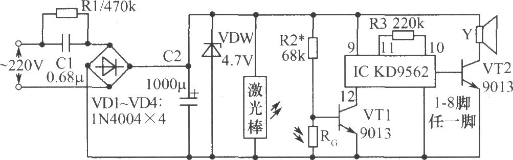
As shown in the figure, the circuit of the detection and alarm device made of the laser rod is shown. The analog sound integrated circuit IC and other components constitute the receiving circuit. At ordinary times, the laser emitted by the laser rod just shines on the photoresistor RG, and the RG is in a low resistance state. The triode VT1 is cut off because of the low base potential. The IC does not work, and the speaker Y does not emit sound. Once someone or object enters the warning area to block the light path, RG resistance becomes larger due to lack of light, VT1 is saturated and connected due to the rise of base potential, IC is powered on, and the output audio signal is amplified by the triode VT2 to push the speaker to send out an alarm sound. Since the circuit is in a low current and long-time working state, the capacitor step-down power supply mode is adopted. After the capacitor C1 step-down, VD1-VD4 bridge rectification, C2 filtering, and VDW voltage stabilization, the mains power can obtain a voltage of about 4.7V to power the entire device.
Related Readings
Popular Circuit Diagrams
Special Sale
