Application Circuit of Integrated Liquid Level Sensor LM1042 in Automobile
Related component PDF download:
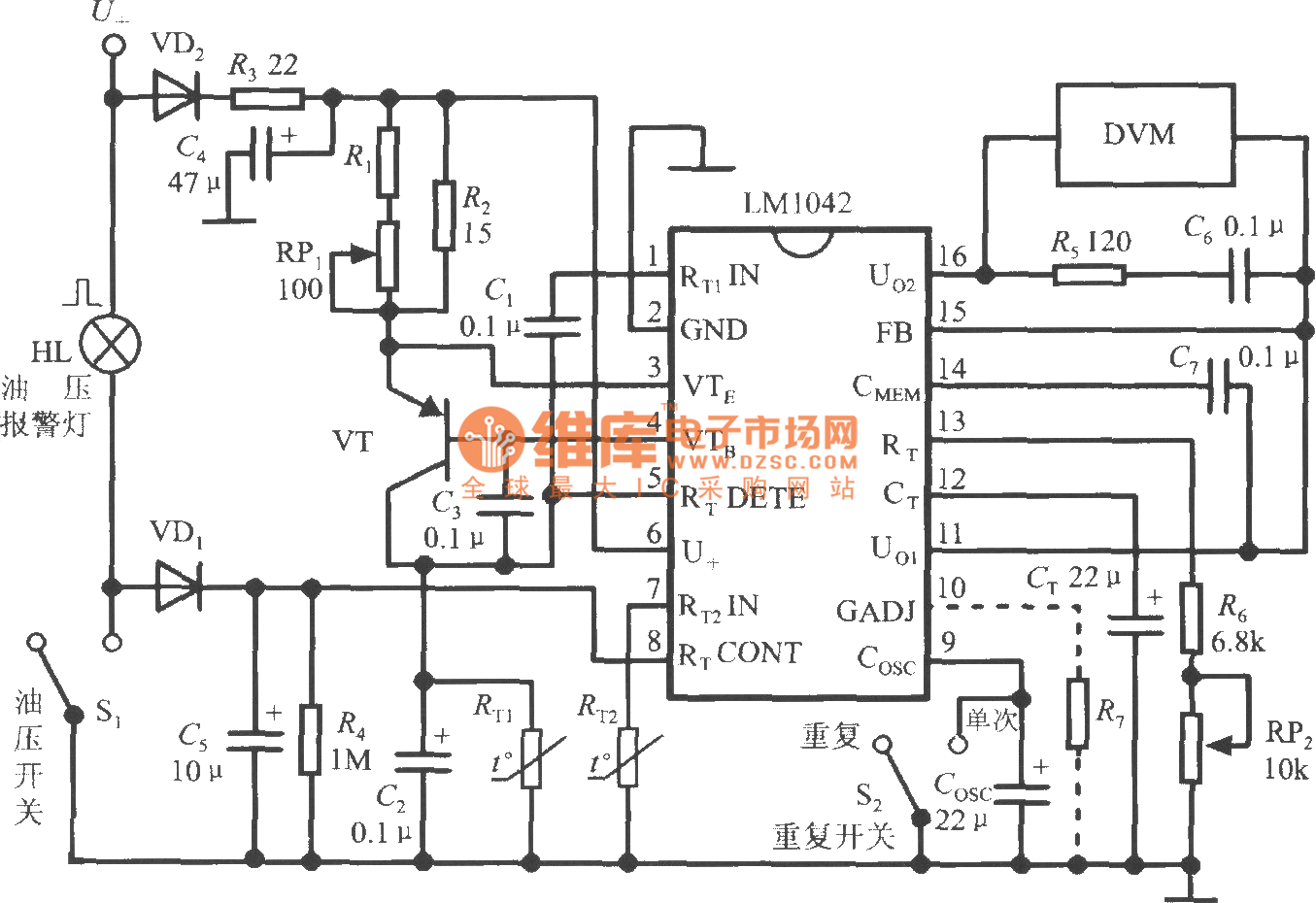
The application circuit of LM1042 in automobiles is shown in the figure. The power supply is taken from the+12V battery. Use the oil pressure switch S1 to select the probe. When the car is ignited, S1 is closed, the 8th pin is pulled to low level by wind, and probe 1 is selected to measure the liquid level in the fuel tank. After the engine starts to work, S1 will be disconnected, U+will pull the 8th pin to high level through VD1, and the auxiliary probe 2 will measure the liquid level. Even if the engine stalls, C5 keeps the 8th pin high, which can prohibit probe 1 from measuring. HL is the oil pressure alarm lamp. VD2 can prevent the polarity of the power supply from being reversed. RP1 is used to adjust the working current of the probe so that I=200mA. RP2 is used to calibrate the duration of each measurement. When S2 is closed, COSC is short circuited and single measurement mode is selected. Select the repeated measurement mode when disconnecting S2. To change the voltage gain of A4, connect the resistor R7 along the dotted line in the figure. The digital voltmeter is connected between Uo2 terminal and Uo1 terminal, and R5 and C6 can be used to filter out the high-frequency interference at the instrument input terminal.
Related Readings
Popular Circuit Diagrams
Special Sale
