A cheap wireless microphone circuit
Source:tjzdh
Recently, a wireless microphone sold in the market was priced between 10 and 20 yuan. The microphone is tuned in the 88~108MHz FM band, and its transmission distance is about 30m. It can be received by any FM radio, and the received sound is clear and pleasant, without clutter interference, and has no impact on local FM radio. I drew the circuit diagram of the machine according to its real object for the reference of electronic enthusiasts.
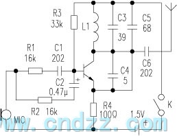
Operating principle of the circuit. The sound passes through the microphone via R1 and C1; The high and low frequency resistance capacitance filters composed of R2 and C2 are coupled to the base of the triode. Due to the positive feedback amplification of the triode, the high-frequency signal of the high-frequency oscillator composed of L1 and C3 is fed back to the base of the triode through C4. The two signals are mixed by the triode to form a high-frequency FM carrier (88 ~ 108MHz), which is transmitted to the antenna through C6, and then the antenna transmits FM signals to the surrounding space.
Adjust the clearance of L1 coil to change the frequency value of FM wave. When in use, FM reception frequency points can be arbitrarily selected between 88 and 108MHz.
Selection of element L1. Use Φ 0.6mm enameled wire to wind 4 circles on the common ballpoint pen center, use C9018 high-frequency low-power transistor for triode, and other components can be identified according to the parameters in the figure.
Related Readings
NRF902 FSK 868 MHz transmitter
 2024-03-31 08:00:00
NRF402 FSK 433 MHz transmitter
2024-03-31 06:00:00
NRF904 FSK 915 MHz transmitter
2024-03-31 04:00:00
RfHCS362G/362F ASK/FSK 440 ~ 310 MHz KEELOQ code hopping transmitter
2024-03-31 02:00:00
RF2942 I/Q 915 MHz transmitter
2024-03-31 00:00:00
Popular Circuit Diagrams
NRF902 FSK 868 MHz transmitter
NRF402 FSK 433 MHz transmitter
NRF904 FSK 915 MHz transmitter
RfHCS362G/362F ASK/FSK 440 ~ 310 MHz KEELOQ code hopping transmitter
RF2942 I/Q 915 MHz transmitter
RfPICl2F675H/F/K ASK/FSK 915/433/315 MHz transmitter
RfPICl2C509AG/509AF ASK/FSK 480 ~ 310 MHz transmitter with 8-bit microcontroller
QFMTl-916.5/868/433.92 AM/FM transmitter module
QFMT6-915/869.85/868.4 FM transmitter module
RF2909 GMSK/QPSK/DQPSK/QAM 915 MHz transmitter
Special Sale
