FM wireless microphone circuit with voltage stabilizing circuit
Source:princesssg
Related component PDF download:
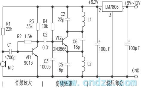
1、 Circuit principle (see the figure below) The circuit consists of three parts: 1. audio amplification part; 2. High frequency oscillation part; 3. Voltage stabilizing part. The signal is injected into the base of the triode VT1 by the microphone MIC, and the audio signal amplified by VT1 is coupled to the base of the high-frequency oscillation circuit VT2 through C2, and then transmitted through the antenna. The operating frequency of this circuit is between 85 and 104MHz.
2、 The MIC selects high sensitivity electret microphone, VT1 is 9013H, β≥ 125. VT2 is 2N3866; β≥ 90, L1 and L2 are tightly wound with Φ 0.71mm enamelled wire on the common ball point pen core for 4 turns and 10 turns respectively, and C4, C5 and C6 are porcelain chip capacitors with an error of ± 5%. LM7806 power supply and 9V battery are used for the three terminal voltage regulator, and the circuit board can be self-made.
3、 The assembly and debugging of the circuit is relatively simple. As long as the components are not damaged, the installation can be successful. After the circuit is soldered, the antenna is soldered on. The antenna uses a 0.5m radio antenna. During debugging, place the microphone at the sound source, and then leave the microphone 5~6m away. Turn on the FM radio and adjust the station selection knob. If the received harmonics are muddy, you can use a screwdriver to adjust the spacing between oscillation coils L1. If the L1 spacing is large, the frequency increases, otherwise it decreases, and then the received sound is not harmonic.
If you want to increase the transmission power, you can change the length of the transmission antenna, or replace the VT2 transmission tube with a 34D50 triode, and the R4 resistance with 4.7k Ω. At this time, the transmission distance can be increased by about 100 meters.
Related Readings
NRF902 FSK 868 MHz transmitter
 2024-03-31 08:00:00
NRF402 FSK 433 MHz transmitter
2024-03-31 06:00:00
NRF904 FSK 915 MHz transmitter
2024-03-31 04:00:00
RfHCS362G/362F ASK/FSK 440 ~ 310 MHz KEELOQ code hopping transmitter
2024-03-31 02:00:00
RF2942 I/Q 915 MHz transmitter
2024-03-31 00:00:00
Popular Circuit Diagrams
NRF902 FSK 868 MHz transmitter
NRF402 FSK 433 MHz transmitter
NRF904 FSK 915 MHz transmitter
RfHCS362G/362F ASK/FSK 440 ~ 310 MHz KEELOQ code hopping transmitter
RF2942 I/Q 915 MHz transmitter
RfPICl2F675H/F/K ASK/FSK 915/433/315 MHz transmitter
RfPICl2C509AG/509AF ASK/FSK 480 ~ 310 MHz transmitter with 8-bit microcontroller
QFMTl-916.5/868/433.92 AM/FM transmitter module
QFMT6-915/869.85/868.4 FM transmitter module
RF2909 GMSK/QPSK/DQPSK/QAM 915 MHz transmitter
Special Sale
