Fabrication of Digital Display High Sensitivity FM Stereo Front End
The sensitivity index of this digital FM FM stereo front-end has reached 0.5, which is still considered high μ V 20dB S/N level, with electric tuning band automatic frequency alignment, no signal squelch, RSS field strength meter indication and other functions, is suitable for long-distance reception of local or foreign FM stereo program broadcasting. The price of its products has caused considerable controversy among domestic radio enthusiasts in the late 1990s. The front stage of the whole machine adopts modular components, with digital frequency display SC3610. The prototype and detailed working principle of IF and stereo decoding circuit can be found in the circuit introduced in Chapter 6 of High Frequency Circuit Design and Production.
 Schematic diagram of the whole machine | ||||||||||||||||||||||||||||||||||||||||||||
 | ||||||||||||||||||||||||||||||||||||||||||||
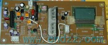
| The whole machine is composed of MG-205V cassette FM radio special front-end component, Toshiba TA730 integrated circuit 3 IF amplifier and TA7343 stereo decoding circuit. The MG205V high-frequency electronic tuner uses voltage control (voltage control) to change the LC circuit parameters to achieve frequency tuning of the radio station. It can interface with the CPU microcomputer chip to achieve automatic tuning, channel storage and other functions. MG-205V module consists of a low-noise double gate field-effect transistor to form the front amplifier circuit, and three high-frequency transistors to form the local oscillation, mixing and local oscillator output circuits. It is compact in structure, uses a large number of SMD chip elements, small in size and stable in performance, and is widely used in many card and car stereos. We will describe each component unit of the circuit separately below. | ||||||||||||||||||||||||||||||||||||||||||||
| ▲ MG-205V FM high-frequency electronic tuner | ||||||||||||||||||||||||||||||||||||||||||||
 | ||||||||||||||||||||||||||||||||||||||||||||
| ||||||||||||||||||||||||||||||||||||||||||||
 | ||||||||||||||||||||||||||||||||||||||||||||
| ▲ Ceramic filter and TA7303P for FM IF The intermediate amplifier circuit uses two ceramic filters to ensure high selectivity. The performance of ceramic filter will affect the performance of this machine, so more formal products should be selected. The model of Murata is SFEl0.7MHz, its 3dB frequency response bandwidth is 28050kHz, and the insertion loss is ≤ 6dB. Murata's SFE 10.7 series has S2, S3, and MJ suffixes, and the bandwidth decreases in turn, all of which can provide more than 35dB of out of band attenuation. The installation and welding of ceramic wavers should pay attention to the directivity. TA7303P is an integrated circuit with three-level differential JF amplification and FM frequency discrimination. Compared with other ICs that we are familiar with, it also has the functions of muting and RSSI table. By selecting TA7303P, we can clearly know the signal strength of our current environment while listening to FM radio. In addition, the annoying FM specific harsh noise will disappear when there is no channel or when selecting a channel. For more information and introduction about TA7303P and FM stereo, see Chapter 6 of High Frequency Circuit Design and ProductionDesign and Fabrication of FM Demodulation/IF Amplification Circuit One wen. | ||||||||||||||||||||||||||||||||||||||||||||
 | ||||||||||||||||||||||||||||||||||||||||||||
 | ||||||||||||||||||||||||||||||||||||||||||||
| ▲ Automatic gain control (AGC) and AFC circuit Since the TA7303P has an RSSI meter output terminal, we will use it to drive the ACC circuit in the BTK-20 high-frequency module. The specific control process is realized by N7 and a few peripheral circuits. The stronger the received signal, the higher the RSSI output voltage of the TA7303P, and the lower the AGC control voltage controlled by N7, thus reducing the gain of the whole machine. In this AGC control circuit, R32 and R33 determine the AGC starting point, and R35 and R36 determine the starting AGC amount. In addition, in order to prevent the negative impact caused by the jitter of AGC response, we add C46, whose value determines the speed of AGC response. Automatic frequency tracking AFC is achieved by some skills. In fact, neither the TA7303P nor the MG-205V module provides a special AFC control terminal, but we can use the DC component (8-pin A point) demodulated by the TA7303P FM to skillfully "superimpose" a resistance to the BTK-20 tuning terminal to achieve the purpose of AFC, without having to fight for the AFC circuit. The impedance of the resistance used for this AFC is generally 470K~2.2M. ▲ Stereo multiple demodulation circuit TA7343AP In stereo restoration circuit, we use TA7343AP, which integrates subcarrier generation circuit, phase comparison circuit and FM frequency discrimination circuit. In fact, the stereo tuner of this machine can also use any 1C that he or she likes. For more information and introduction about TA7343AP and FM stereo, see Chapter 6 of High Frequency Circuit Design and ProductionDesign and Fabrication of FM Stereo Demodulation CircuitOne wen. Its performance parameters will not be explained in detail here. ▲ Frequency and clock display drive circuit SC3610 SC3610 is a frequency and clock display circuit, which is used to display AM/FM frequency and 12 hour clock. It is made of CMOS technology and has the characteristics of low power consumption in the clock display mode. SC3610 has a variety of packaging types, and its SOP packaging specification is used in this production. Main features: FM front-end input with prescaler can input a display frequency of 150MHz The display frequency that can be input at AM end is 30MHz LCD display drive structure: three common pole drives,? 3 character segment drive, 1/3 offset, 4 digit display drive On chip oscillator with external 32 768 kHz crystal oscillator For FM signal, IF frequency compensation is 10.7MHz or 70KHz, and for AM signal, IF frequency compensation is 455kHz The internal clock is displayed in the 12 hour display mode, and the clock or frequency display options are available Working range of power supply voltage: 2.8V~3.3V | ||||||||||||||||||||||||||||||||||||||||||||


Download PDF documents:
 |
 |
| (SC3610 typical application circuit and independent application unit PCB) Circuit schematic diagram |
Selection and manufacture of components of the whole machine The whole receiver adopts high-quality single-sided glass fiber printed board, all resistance devices adopt the l/16W specification and are installed horizontally, and the ceramic chip capacitor with small capacity should also choose the horizontal tubular AXIAL 0.3 specification. The shell of the corresponding pin 1 of the ceramic filter is marked with a circle point. It should be noted that this is the input end. The 102 capacitor of the four pins of the TA7343AP has a direct impact on the output sound quality due to the stability of stereo decoding design, so polyester capacitors with good temperature coefficient should be selected. The potentiometer used for tuning and selecting platform is often twisted to achieve the purpose of tuning. It should be made of multi turn potentiometer, wire wound or glass shaft material. Although this type of potentiometer is expensive, it has reliable long-term use performance. Of course, if the AFC automatic frequency tracking quantity is selected sufficiently, the general potentiometer can also be used. ▲ LCD screen and "Zebra Connection" and amateur hot pressing tools The discovery of liquid crystal was completed 100 years ago by Austrian botanist F. Reinetzer, and its application in electronic products was completed in 1961 by the young electronic scholar F. Heimeier of Princeton Laboratory of RCA Company in the United States. LCD is mainly divided into TN, HTN, STN, FSTN and other series according to its imaging mode, working voltage, etc. The specific LCD screen components are generally dedicated. For example, the LCD screen we are preparing to use here is the TN type ultra-low voltage drive model specially designed and produced for the SC3610. If it is replaced by the LCD screen in the general sub meter or the general standard product, it will cause problems such as no display or missing fields. |
 |
LCD low-voltage LCD display, "Zebra Connection" and amateur hot pressing tools for SC3610 Equipment supply  |
Complete machine assembly and commissioning After the components of the whole machine are assembled and confirmed to be correct, connect the ammeter in series to power on and observe that the current of the whole machine is no more than 80mA before the following commissioning: Connect the machine with short antenna, audio amplifier, horn and RSSI meter. Any voltmeter with a range of about 2.5-5V can be selected for RSSI meter. The IF signal strength is 20dBµ- 100dBµ When the range changes, the RSSl output of the TA7303P is between 0-5V. If a small range voltmeter is selected, it can be adapted by adjusting the VARl. The broadcast of FM radio station can be heard immediately after power on tuning. If not, check the working status of TA7303P first. If there is no oscilloscope and other equipment, touch its input end with a metal pinch, you should hear obvious sand - interference sound and even chaotic radio signals. L5 is a key component in the intermediate amplifier frequency discrimination circuit, and the adjustment is also very simple. When the radio station is received by the whole machine, you can use a non inductive driver to turn L5 until the RSSI meter indicates (at this time, the stereo indicator LED should be on), or you can adjust the noise of the horn when there is no station and no noise. The voltage at the VT end of the MG-205V assembly determines its receiving range, which has been clamped by R15 and R17. Due to the unity of component production, no more effort is needed here. The AFC uses resistance to determine the automatic tracking range of the machine's frequency, which is generally about 1.2M, and the corresponding AFC range is about 150kHz. If the resistance value of the resistance is reduced, the AFC range will be correspondingly increased, but this may lose some of the gain of frequency discrimination. VAR2 determines the start control threshold of "mute" when there is no station or when searching. You can adjust it until the harsh FM noise just disappears when there is no station, or you can install VAR2 separately from the panel and adjust it as appropriate. When the whole machine is used for receiving remote FM radio stations, the IF circuit should be equipped with a double-sided shielding box, which can increase the sensitivity of the whole machine by about 6dB. Roughly estimate the assembly quality and performance indicators of the whole machine. The method is to completely remove the antenna soldered on TPl, and rely only on the signal sensed by the circuit board. In urban areas, if the machine can still listen to FM radio well and move indoors without too many dead corners, then it can be considered that the machine has reached or basically approached the level of a first-class receiver. |
 |
 |
| (This PCB ink draft is a 1:1 drawing, and the laser printer can also be used to directly produce and prepare the board) |

Related Readings
Popular Circuit Diagrams
Special Sale
